The lines from the start (green) to the circle and the rectangle are used to drive a few millimeters into the styrofoam before beginning. (This DXF file should be somehere in the examples section)
Released under the GPL; Michael Abel (C) 2007
Dxf2quad converts DXF files into quad-column coordinate Files
(Quads) for the foam-cutting application FoamBlade. Like FoamBlade
dxf2quad is optimized (built for) for 4 axis hot-wire cutters.
FoamBlade uses so called Quads as file format. Each line in a Quad
contains a row of four numbers. This four numbers (x,y,u,v) are two
dimensional coordinates (xy and uv) for each of the both cutting
units.
The cutting procedure in Foamblade processes such a
Quad row by row. In the beginning it is assumed, that the machine is
currently at the coordinates in the first row of the Quad. The
machine drives then to the coordinates in the next row. After that
the machine drives to the coordinates in the following row, and so
on. The "space" between two lines is linearly interpolated
and the cut-speed is chosen so that both machine units reach the next
coordinates exactly at the same point in time. To cut nice bows and
circles it's of course necessary to use lots of rows with a small
distance between them.
For example: cutting a box just needs
four lines in the Quad. But for a big circle I would recommend around
thousand lines to get it smooth enough. Smoothness can be controlled
via points per subgraph (explained later).
In FoamBlade-Interactive it is possible to create, read, edit, modify Quads and 2 Dimensional Coordinate files (like *.dat). Lots of Functions can be applied on quads like interpolation, intelligent separation, repetition. But dealing with real huge and real complicated pathes is annoying. That's why we had the idea to use a graphical editor to construct the paths easily. Since I found no suitable program that was able to create usable cut-paths, I wrote dxf2quad. With this converter it's easy to use a standard CAD program and "paint" the cut-path.
The Idea of dxf2quad is that one can use a 2D CAD Program to
construct the parts that he/she likes to cut. Currently this is done
via constructing the paths that both cut units should drive along.
Since we have two cut units (one at each end of the wire) we need to
construct two paths, too. If you for example want to cut something
like a cylinder which is round on one side, but has a rectangular
shape at the other, you will need to paint a circle as path on one
side, but a rectangle at the other side. Which objects belong to
which side can be controlled by the layers containing the objects.
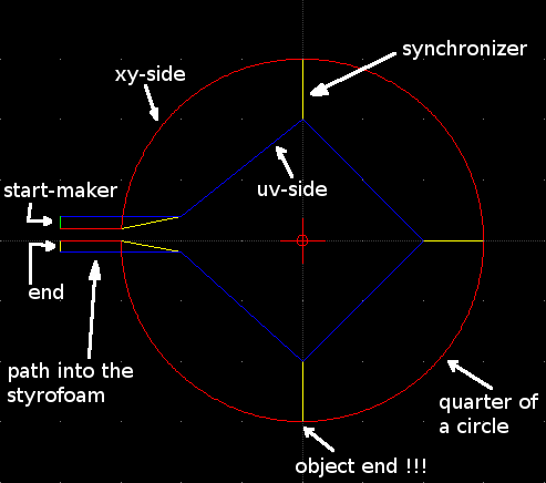
Some additional information apart from the both cut-paths has
to be painted into the cad file. Especially the synchronization, that
controls the way the path is cut, has additionally to be constructed,
too.
If we just drawn two paths for xy and uv into a DXF file, there would be no information about the timing of the cutting procedure. To overcome this problems it's possible to use special synchronizers in dxf2quad. The meaning of such a synchronizer in the path is such, that both machines units have to reach the coordinates at the ends of the synchronizer at the same point in time. Easy spoken it is a snapshot of the wire on the path. With the additional information from the synchronizers dxf2quad can derive a cut-path with the correct timing.
We want to paint a complete cut-file with synchronizers, thats the graph. The graph is self is separated by synchronizers into subgraphs. A subgraph consist of objects between two synchronizers. The precision of the cut-file generation can be controlled by the amount of Quad lines that are used to represent a subgraph. As default value 100 lines are used. The value that you need depends on the amount of synchronizers in your Path. Many synchronizers reduce the amount of lines per subgrah that are needed.
DXF files are by definition graveyards of codes and numbers. Getting information out is sometimes not that easy.
Up to now only Ribbonsoft's QCad and AutoCad are tested.
Currently usable objects are lines, circular-arcs and elliptic-arcs. Polylines will be usable soon.
Complete circles and ellipses are not allowed, because they have no begin and no end.
Coming soon objects are splines
Length unit is millimeter (mm)
Dxf2quad uses layers to distinguish between objects that
belong to the cut path and objects that are synchronizers.
The xy side of the path has to be on a layer named "xy". I recommend also to use the color red for this side.
The uv side of the path has to be on a layer named "uv". I recommend also to use the color blue for this side.
For laziness it is possible to use a layer named "xyuv" or "both" if xy and uv lie exactly on the same path. I recommend violet as color here.
Synchronization Objects have to be on a layer named "sync". I recommend yellow here.
There has to be exactly one start marker on a layer named "start". I recommend green here.
Additionally to layers like "xy" it is possible to use layers named "xy_****". This makes the construction of complex paths more easier.
Objects on other layers are just ignored.
The path shall begin with a start marker.
Then one or more Objects can be put on the xy and the uv path one after another. Currently minimum one.
At some time you want to synchronize both sides and paint a synchronizer.
repeat the steps 2 and 3
Be also sure that the end of the path is also synchronized.
Construct the paths on both sides according to your problem.
Add a start marker.
Synchronize where it seems to be necessary.
Synchronize in the end, too.
In the end this may look like this (cylinder with a rectangular
side (previous example)):
The
lines from the start (green) to the circle and the rectangle are used
to drive a few millimeters into the styrofoam before beginning. (This
DXF file should be somehere in the examples section)
Path building is very strict because dxf2quad has to search for objects that fit together and is too dumb to resolve conflicts or errors.
To define that two objects belong together they have to end at the same point
Objects that shall end on the same point have to be on the same point (use a grid,or a snap to point feature)
Annotation: AutoCad nevertheless seems to displace Points. Maybe you have to zoom in and correct the positions of the points manually
Dxf2quad looks only at the ends of objects. This means that, when it is searching for objects it can only find connections where objects have ends. If you for example want to place a synchronizer end on the middle of a line you have to split the line into two parts. Afterwards you have to place the synchronizer exactly there were both lines meet.
To construct a path with lines that are driven more than once (maybe in two directions) displace both lines maybe a 1/100 mm
(This is the preferred way.)
Install Python from www.python.org (If you not already have it).
Execute the script fbv.py or use (FoamBlade to execute it)
Windows: Doubleclick fbv.py
Linux: Execute ./fbv.py on a shell, or use a graphical tool to execute it.
Press the "Scan DXF" Button
Open a DXF
Adjust the points per subgraph, if necessary.
Press Start
Correct eventual errors
If you have no errors you can return to the Viewer and do a simulation
If you want, you can save the Path as a Quad, but thats not really necessary, since FoamBlade can read the DXF, too.
Extract the dxf2quad archive
Open a Terminal/Shell-Window
Go into the dxf2quad directory
./dxf2quad.py <infile.dxf> <outfile.quad>
or
python dxf2quad.py <infile.dxf> <outfile.quad>
(I hope so)
Extract the dxf2quad archive
install python from www.python.org
Execute “cmd” or open an Dos prompt
add python to the path
path %path%;<python_path>
change to the dxf2quad directory
python dxf2quad.py <infile.dxf> <outfile.quad>
example for a German WinDos:
path %path%+c:\python25
cd "Dokumente und Einstellungen\Admin\Eigene Dateien\dxf2quad"
python dxf2quad.py pathes\allObjects.dxf pathes\allObjects.quad
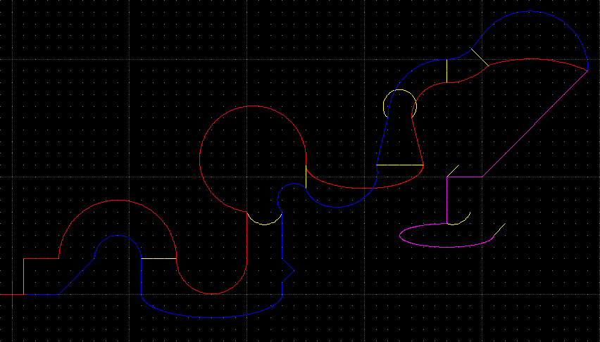
This dxf is also in the paths directory it shows nearly everything
that is possible with dxf2quad.
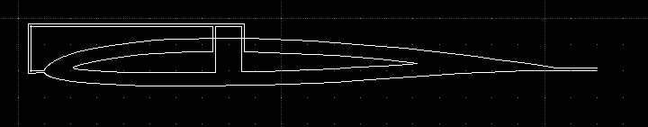
This is a slightly complexer example that shows how it is possible to cut
an partly hollow airfoil.
The first picture shows only what I had
in mind when I did this:
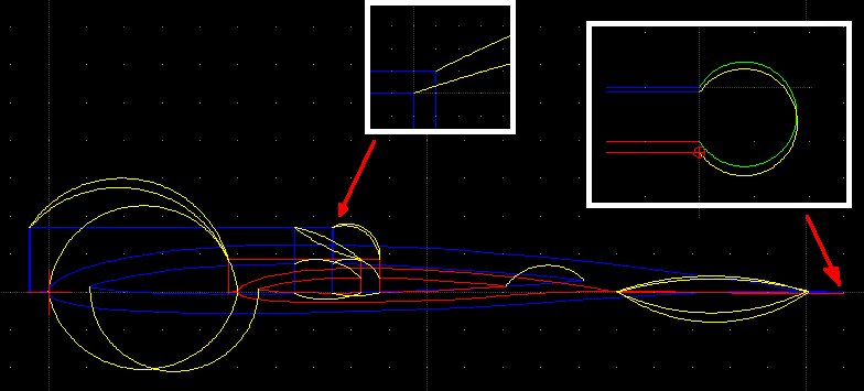
The
second picture here is the complete cut-path where the xy side is
scaled additionally:
This
is the newest creation a zagi:
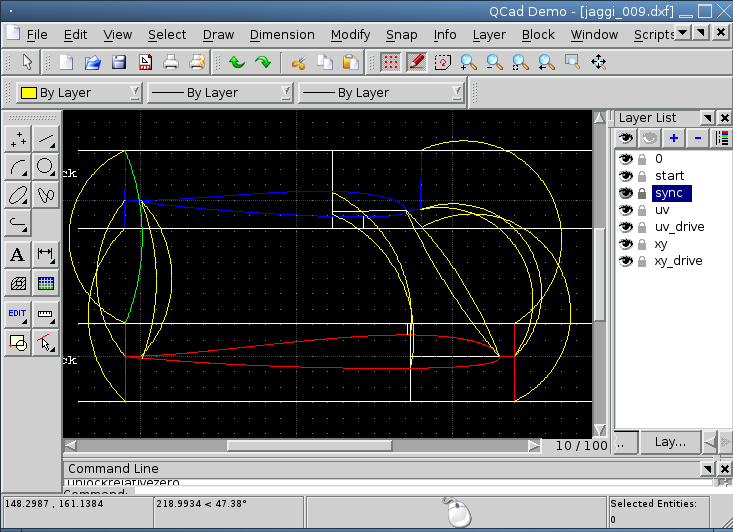
The
5cm Styrofoam block, that is used is painted in white. The
Stryro-Block is also cropped at the front and back side while
cutting. With this the parts below and on top of the wing part can be
used for several reasons, too.
QCad: http://www.qcad.org/ (RibbonSoft)
FoamBlade: http://foamblade.sourceforge.net/
Python: www.python.org
Me: mabel äät quasiinfinitesimal.org