The FoamCut Framework

This document is intended to give a short overview over the FoamBlade Framework
About me: Im no aviation specialist :). Copyright 2007 Michael Abel
last update 8.4.07

0. What you will need:

For Path Creation:
Since Python is Platform independent FoamBlade should run on most Systems. On Windows(Mac?) there might(will) be problems with the Viewers that use GTK. Maybe FoamBlade runs with CygWin under Windows (Report me if you have tried it). I run FoamBlade under Debian-Sarge and Ubuntu.

Install following packages:
python
python-gtk
python-glade
scipy (and the automaticaly selected packages)
numpy (Numerical Python) ... Numeric???
mathplotlib

For cutting:
You will additionally need a Linux with Rtai (Realtime Application Interface) Extension.
See The Ubuntu Howto If you want to use a ready realtime Ubuntu.

If you run into problems: There is also a small Ubuntu Howto that conains maybe useful information.

Hardware:
A Hotwire Cutter :)

A Stepper motor interface:

Nearly every parallelport interface should fit if it uses direction-step control ( here called clockbased). Fluxbased motor control (the pin value sets the current direction trough the solenoids) will be implemented soon(mail me if you need it).
Maybe there are a few necessary adjustments to your pinout (mail me, I try to integrate them), complete softwireing comes soon.

We use a step3D Interface from
http://www.nc-step.de/step3d.html


Up to now used pins
-pin 2 to 9 for Motor Control ( soft wireable in MachineConfig.py)
-pin 16 =High can be choosen by giving HotWire the parameter --step3Dboost

1. General:

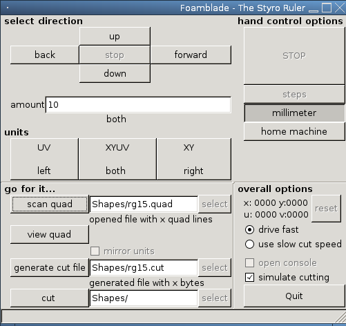
FoamBlade is a framework that provides a full toolchain for hotwire foamcutting. It can be used to create, modify and cut so called cut-pathes. A hand control is also integrated. FoamCut currently supports some 4-axis hot-wire Foamcutting machines driven with stepper motors that are connected to the parallel port.
You can use it for example to cut parts of your model aircrafts. See the examples or the Project Homepage af sourceforge.

At current only clock based parallel port interfaces can be used for cutting. The parallel port is controlled from a Linux machine with the RTAI ( Realtime Application Interface) extension.
A GTK (Gnome) Gui is used for hand control and cutting and an interactive session is used for creating and modifies pathes.

As you maybe have expected by reading the above Linux is the OS of choice at this time. If somebody wants to port Hotwire (see below) to another OS some things might get easier. Feel free to port also the GUI to your OS of choice. Please contact me if you plan to port something.

There is also a Howto available that describes how to get FomBlade working in an realtime Ubuntu. See : Ubuntu-Howto.html

What is Foamblade?

Foamblade is used to read, create, modify and write several "Pathes". In the end you get a so called cutPath in a file that can be cut with Hotwire. Foamblade is written in Python and uses PyGTK, Glade, ... and your CPU.
You can also use Foamblade in an interactive Python session for advanced Path creation.


What is HotWire?

Hotwire is the program that eats the cut files created by Foamblade. After that it writes the content of the cut-file in realtime to your parallel port to control your cutting machine.

Every time you use the handcontrol in FoamBlade or cause that file is cut HotWire is started in an extra shell window.

To stop HotWire select the HotWire Window and press "Q" or Escape.

By default foamblade sets the hotwire simulation to true, to deactivate simulation mode click onto the "simulate" checkbox. To use Hotwire in non-simulation mode you need to be root and you need to have the modules rtai-hal and rtai-lxrt loaded. Additionally you should deactivate everything that communicates with the parallelport. There is a bash script named init.sh in the HotWire source directory to do (try) this for you.

Viewer:

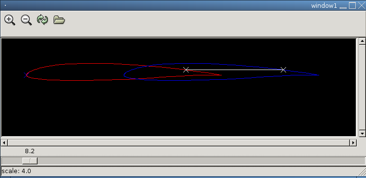
The Viewer is a nice small tool to view quads and steplists. As an extra feature you have the ability to trace the wire movement in your your cut path as cut simulation.

The viewer marks the origin with a small colored cross.

Note: Due to a bug in the Viewer one has to press the update button after scaling.


ViView:

fixme

plView:

fixme

Acknowledges seomething to mention:

think whatever you want, but this is true here:

You want to have a "unit" at each end of the hot wire.

xy : right unit x: horizontal y: vertical
uv : left unit u: horizontal v: vertical


motion forward =positive
motion upwards =positive
mathematical positive rotation= counterclockwise

2. About the PathContainers

General dataflow overview:


airfoil file
( mostly *.dat )
DoubleColumn QuadColumn
read and writeable as
*.quad
StepList CutPath
read and writeable as
*.cut
go and cut it


Everyone of the PathContainers supports reading to and reading from files and other general methods. Additionally a PathContainer can convert itself into the next PathContainer in the chain. Some of them support other modification methods like scaling, interpolating or printing in the viewer.

Path modification commands

There is a fairly complete command reference for the interactive Session: FoamBlade-Commands-0.03.html

See the Methods defined in "class QuadColumn and class DoubleColumn" in PathContainer.html( in the FoamBlade doc Directory) to get a up to date list.
To call them leave the self -parameter away.

DoubleColumn:

Contains numbers in two columns. Most standard foils can be read into a DoubleColumn. Be careful some foil files contain a few numbers in the beginning that are sometimes read as coordinates. Some others contain the points in different orders (use a Text editor to correct that now or later)

read a line in the file as " x y"

QuadColumn:

Most important Container in this chain. It contains the path to cut with synchronized coordinates lines. Of course for each side of the cut machine, therefore it consists of four columns. If you cut a quad the machine drives linewise to the xy coordinates on the right side and to the uv coordinates on the left side. The space between the "lines" is later interpolated linear to machine precision. The coordinates should be so dense that a linear interpolation is precise enough.

If the drive distance of the right unit differs from the one on the left unit: The side with the longer distance is cut with the adjusted cut speed and the side with the shorter distance is cut slower. As a consequence both units reach the next coordinates (in the next line of the quad) at the same time.

A quad File can also easily edited in an text editor. I mention it because you have sometimes to look into one and maybe change or add a line.

The numbers in the quad are understand as coordinates in millimeter.

read a line in the saved file as " x y u v"

I'm often lazy and use only "quad" instead of QuadColumn.

Every line that couldn't parsed( doesn't contain 4 Numbers) is taken as comment. Since it indicates a good style try to use only blank lines and lines that begin with a '#' sign as comment.

Example:
This is a quad that I use sometimes to find the correct speed and current for a material. Since it cuts the same on both sides you can see only one line.
speed-test.quad:
0		0		0	0
0		-10		0	-10
100		-10		100	-10
100		0		100	0
100		-40		100	-40
90		-40		90	-40
90		-30		90	-30	
80		-40		80	-40
80		-30		80	-30
70		-40		70	-40
70		-30		70	-30
60		-30		60	-30
60		-40		60	-40
50		-40		50	-40
50		-30		50	-30
40		-30		40	-30
40		-40		40	-40
30		-40		30	-40	
30		-30		30	-30
20		-30		20	-30
10		-40		10	-40
0		-40		0	-40
0		0		0	0


StepList:

Contains an interpolated quad with a line for each step that is done while cutting. Since it contains the absolute step numbers a StepList resembles to a quad apart from the fact that it is enormous large and contains very large numbers. This could be important for debugging because you can open a StepList in the viewer and look what the interpolation did. But remember that you probably look a very large file with steps in machine precision which makes the viewer maybe very slow.

Since you don't need the StepList only to convert it to a CutPath you don't have to write it to a file.

CutPath:

Contains that what you wanted: the cut file depending on your cut machine. Every line contains a byte as a hexadecimal value that is later send to your parallel port cut machine while cutting.

The size of this file can be easily calculated:
A line is for one machine step. A line consists of three bytes ( two for the hex value and a newline). When your Path is L millimeters long and your machine resolution is A steps per millimeter:

Size[Bytes] = 3 * L * A

3. Configuration

fixme Take a look into MachineConfig.py it's roughly described there.

4. Gui Usage HowTo

fixme

5. Interactive Session HowTo

This ">>>" is the Pyton prompt that is shown in an interactive python session. Since foamblade uses the interactive python session this prompt is shown in an interactive foamblade session
Most of the Operations you can call return objects that you should save like this:

rg=QuadColumn('Shapes/rg15.quad')

rg is now a variable that contains an instance of the QuadColumn class, that means rg represents now a quad
Later you can use this objects to call Operations like this: rg.addOffset(0,0,-150,0) (Tis operation shifts the left side to obtain a sweep)

Be also sure that there are no spaces before the command you typed (python uses them for grouping).

>>>  q.rotate(0,0,0,0,10,-10)
  File "<stdin>", line 1
    q.rotate(0,0,0,0,10,-10)
    ^
SyntaxError: invalid syntax
>>>
>>> q.rotate(0,0,0,0,10,-10)
>>>
An example session

Fist chdir to your FoamBalde directory and execute ./interactive.sh

$./interactive.sh
starting interactive Foamblade session
your Machine is named mach
ready
>>>

Read a double column. You can skip this if you have already got a quad.
>>> d=DoubleColumn('Shapes/rg15.dat')

Create a quad from the data in the double:
>>> q=d.convertToQuadColumn()

Scale the left side a bit (the right side is scaled with factor one).
>>> q.scale(1, 1, 0.8, 0.8)

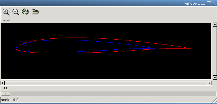
Use the nice Viewer to look what is in the file:
>>> q.view()


Eventually modify the quad (see below) to your needs either using a quad-Operation or write it back to file and edit it with a text editor. The Text editor trick is still needed since foamblade has up to now no embedded editor.

Edit it the path with an editor, save it and reread it again in the same session:

>>> t.writeToFile('Shapes/path-pre.quad')
>>> w=Quad('Shapes/path-pre.quad')

Since the following commands, that create a cut-path fro a quad, are everytime the same the foamblade gui has an own button for this :).

>>> s=q.convertToStepList(mach)
>>> c=s.convertToCutPath()
>>> c.writeToFile('Shapes/rg15-mod.cut')

If you need help try something like this
>>> help (QuadColumn)

Example Session: Zaggi


a bit outdated sine a few things are easier now

Here is the full(rather complicated) creation process for a (?) wing only airplane. I did the trick that the wole airplane is cut in one process so don't get confused :).

Command Comment
$ ./interactive.sh
starting interactive Foamblade session
ready
#pull out the blade
>>> d=DoubleColumn('Shapes/pw51.pro') #at first get a nice airfoil
>>> q=d.convertToQuadColumn() #convert it into a usable quad
>>> q.view() #It begins to cut at the end of the foil, Ok
#Make also sure that the coordinates do not
#jump around.
>>> q.printContent() #take a look at the numbers, you have to scale them later
>>> q.getDimension()
object size: 100.0 8.898 100.0 8.898
#it has 8.9% thickness
>>> q.mirror_xu(50,50) #flip it horizontally
>>> q.view() #do this often!
>>> q.writeToFile('Shapes/pw51.quad') #save copy to file
>>> u=QuadColumn( q.getContentList() )
or
>>> u=Quad(q) , works now too.
#make also a backup copy to use it later
#you could also read it from file.
>>> q.scale( 2,2,1.5,1.5)
>>> q.getDimension()
object size: 200.0 17.796 150.0 13.347
>>> q.rotate(0,0,75,6.65,0,-1.5) #rotate the left foil around its middle point
>>> q.view()
>>> q.displace(-1,-1) #add what the wire burns away
#check out the direction (The algorithm has no idea about inside or outside of the foil, it just displaces in a direction)
#if it doesn't fit (see the next command) load the file again, or use a
#copy and use a positive value
>>> q.getDimension()
object size: 201.0162 19.7960 151.0162 15.3470
The foil has to be thicker after a displacement to an outer direction :).
>>> q.writeToFile('Shapes/pw51_scaled_displaced_1mm.quad') Write this to a file for future purposes
>>> q.addOffset(10,0,10,0) shift the complete path 10mm in x,u direction
>>> q.writeToFile('Shapes/pw51_scaled_displaced_1mm_offset.quad')
>>>
>>> u.mirror_yv(0,0) #go on with the next wing ( remember up- and underside are flipped)
>>> u.view() #Oh, see next line
>>> u.reverse() #Begin to cut with the underside that is now at the upside
>>> u.view()
>>> u.writeToFile('Shapes/pw51_upsidedown.quad')
>>> u.scale( 2,2,1.5,1.5)
>>> u.writeToFile('Shapes/pw51_uo_scaled.quad')
>>> u.view()
>>> u.getDimension()
object size: 200.0 17.796 150.0 13.347
>>> u.rotate(0,0,75,6.65,0,1.5)
>>> u.view()
>>> u.displace(-1,-1)
>>> u.getDimension()
object size: 201.016178886 19.7959687413 150.990936148 15.6145707681
>>> u.writeToFile('Shapes/pw51_scaled_uo_displaced_1mm.quad')
>>> u.addOffset(240,0,240,0)
>>> u.writeToFile('Shapes/pw51_scaled_uo_displaced_1mm_offset.quad')

From now on you have to use a Text editor to split the foils in the middle and copy them together according to the plan. This will be easier in following versions.

First step: copy everything together in the right order:

z=QuadColumn('Shapes/zaggi-plain.quad')
z.view()


eventually correct a few wrong end points with the text editor. And add add some lines you like to cut. You can leave the FoamBlade session opened and read the new created files on the fly.

I like to begin to cut at the top of the styro-block therefore I begin with a path downwards. Its also a good idea to drive to the object you want to cut with the same speed on both axes. To obtain this you can for example add a line that begins on both sides 10mm away from your object.


.
.
.
230.6697		-1.1078		230.7192		-2.0284
#this  is cut with different speeds
#10mm near to the next
220.9959		-0.0905		170.7934		-2.0776
#this is cut with equal speeds since it's circa the same length on both sides

#important object
210.9959		-0.0905		160.7934		-2.0776
210.9655		-0.343		160.7603		-2.2963
210.8839		-0.6654		160.681			-2.5727
210.7562		-0.9661		160.562			-2.8299
.
.
.
>>> z=QuadColumn('Shapes/zaggi-ready.quad')
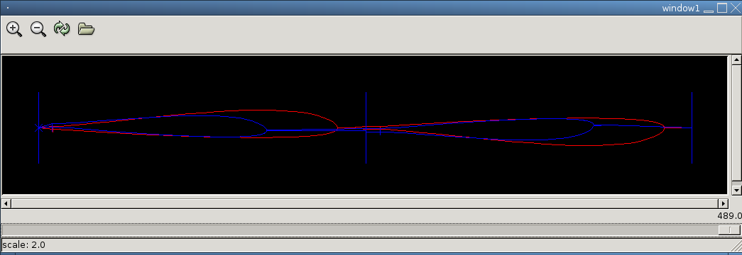
>>> z.view()
...after a few repetitions


And now go and convert the quad to something real!
This example file (zaggi-micha-new.quad )is also somewhere in the Shapes directory

Don't forget the sweep. You have drive the right unit 200mm to the front, to obtain the right sweep.


If you read everything carefully (I know you did :) you might obtain something like this:
zaggi-block.jpg
zaggi-middle.jpg
zaggi-end.jpg
zaggi-top.jpg

What you still can't do with Foamblade

Done: Different aifoils on different sides. Because the airfoil files can differ very much from each other.
That works now but is tricky sometimes. Doku is comming soon.

Read complex data from CAD systems. (Work is in progress)
Scanning points from DXF-files is working now :

1)You have to put lots of points onto your cut path in the order you want to cut. Use several layers to separate various pathes from each other. The Points sould be denser at corners, if you plan to use Spline intepolation, to avoid oscilations
2)save the dxf
3)call "$python dxfparser.py filename.dxf > filename-all.double "
filename-all.double contains now:
...
Layer back-inside
25.000000 -0.000000
25.063812 1.657557
...
25.004973 -0.462941
25.000000 -0.000000
Layer front-outside
21.054560 -0.000000
21.063377 1.049753
21.096900 2.299934
....
4)open filename-all.double in a text editor and separate the pathes front,back etc. from each other and save them into *.doubles
5)process the doubles in FoamBlade into useable Quads ( it's a good idea to do also a Spline Interpolation)

This is a example log that shows the commands to get a quad from 4 doubles
The two fist doubles form the outside of the Extra-body and the last two form the inside of the body. In the end they are put together to cut the inside and then the outside part in one cut.

>>> e1out=DoubleColumn('../Extra/E-1out.double')
>>> e2out=DoubleColumn('../Extra/E-2out.double')
>>> qout=e1out.composeQuad(e2out)		#uses the spline
>>> qout.plView()
>>> qout.writeToFile('../Extra/Extra-front-outside.quad')
>>> e1in=DoubleColumn('../Extra/E-1in.double')
>>> e2in=DoubleColumn('../Extra/E-2in.double')
>>> qin=e1in.composeQuad(e2in)
>>> qin.writeToFile('../Extra/Extra-front-inside.quad')
>>> qin.appendPath(qout)
>>> qin.plView()
>>> qin.writeToFile('../Extra/Extra-front.quad')

Fini


Yes, mail additional comments, questions and feature requests to the friendly author.

Mail to the one that is responsible for this bunch of wrong english here

Valid HTML 4.01 Transitional